Translate

Tuesday, December 2, 2014

The Revit Concept - Past and Future

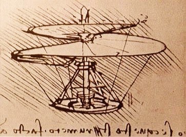
LeCorbusier's Modulor
Revit is conceptual; it is a software tool for virtual modeling in the practice of architecture that, for me, is at once a new paradigm and a revival of an older way of thinking.  The new tool, variously called "Building Information Modeling," (BIM), or "Virtual Design and Construction" (VDC), has been a welcome change in the field.

The Beginning

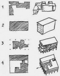
When I studied architecture in the late 1970’s at Cornell, I learned from the work of the modern masters: LeCorbusier, Mies, Wright, Aalto, Kahn, and some newer folks: Meyer, Stirling, Rossi, and others. Thanks to professors Colin Rowe and Mathias Ungers, we were also pointed back to the great precedents before the modern era, and pointed forward to the larger world around us. Design started with criteria for the program and the context. A parti, the big idea, was diagrammed and tested. Architectural elements, including walls, floors, roofs, and openings, built on the parti. These were the elements of architecture , with the designer sketching, drafting, and rendering, and, at times, building a physical model to work out the idea.

The CAD Era

Shortly after I went into practice in the 1980's, the digital age brought a new, helpful, but demanding tool into architecture: Enter Computer Aided Design and Drafting (but with special emphasis on “drafting”). Not purpose built for Architects, CAD had its beginnings in Aerospace. Any discipline could use it for any kind of delineation (I remember my surprise when I saw "Ångström" as one of the choices for setting the units, not just feet or meters). A new vocabulary came to dominate our work: Point, Line, Layer, Xref. The tool brought incredible accuracy, but its narrow focus often distracted from forming ideas and buildings.

CAD came to dominate how we developed designs and produced construction documents, taking the place of the team of hand drafters of past eras. Most simply used it for more efficient 2D drafting. AutoCAD did offer awkward 3D tools within its software packages, but these would go largely untapped. Outside applications crept in, like Sketchup and 3DMax, out of sheer necessity to see the building more fully. Adding and scheduling elements of the building remained a "one item at a time" process, with some assistance from the copy command and spreadsheet software. The computer had automated and integrated the working process in many fields in the 1980's and '90's, but not in architecture.

Back to the Beginning

By 2000, advances in computing started to offer a practical road back to the original focus of architectural design, and leave traditional drafting behind. Architects could begin to work directly in an integrated environment of the virtual building model that completely linked information, and creating a wide variety of 2D and 3D views automatically. When I became aware of Revit as one of these new accessible BIM packages 10 years ago, I jumped in. Away with machine drafting to trace out buildings in in a complicated sequence of glowing vectors and color coded layers. I missed architecture.  

Since then, I have been immersed in the virtual building information model. I am back to the conceptual basic building blocks of wall, column, floor, and roof. I now mold and describe forms, space, and functions as I learned in school. Endless cross references from drawing to drawing update themselves as details shift and change. I am writing this blog, Revit Reflections, to explore ways Revit has energized my work as an Architect, and, in many ways, brought me back to my roots.
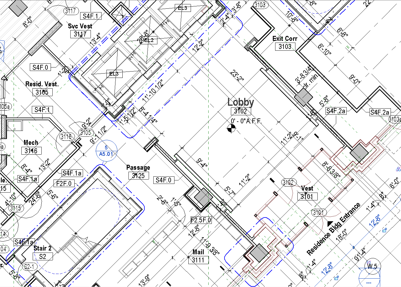


Thursday, November 20, 2014

The BIM Placeholder - Hold that Thought!


Architecture is broad in conception, but also intensely detailed.  Two distinct forms of thinking are needed to get a design off the ground and a building into the ground.  To resolve a design, the architect must branch out and explore, but also refine and nail down. Architects have a long tradition of how this process works: loose sketching of options, expressing  and presenting proposals for debate, for decisions.  Finally, design complete, there is a hand-off, and the process of committing to hard lines and exact descriptions begin.  Narrowing down is relentless, so that the many interconnected details can be addressed. Proceed one step at a time, and, above all NO CHANGES to the design. This split promotes two cultures in any practice: the dreamers and the realists, each working in a separate room.

The computer helped relax the thinking process in many fields. A writer of old would write by hand or peck on a typewriter, then wrinkle the paper into a ball, and start again. Editors with edits and printers with proofs each came in strict succession. A somewhat different workflow than now when using MS Word. We have become accustomed to an interactive process.  

Enter the Building Information Model. Architects compose and link a network of objects to describe the design, giving the building coherent form, proportion,enclosure, structure, functions, and so on. The schematic design serves as the overarching outline of placeholders for a large amount of detailed information that will eventually be resolved.


Schematic Design
Peter Cholakis, in his Building Information Management blog describes it:  "Some information is more appropriately located in the ‘geometrical’ part of the BIM object while other information is more suited to the ‘properties’ part, such as the specification. The specification is part of the project BIM, and objects live in the specification. In traditional documentation we would ‘say it once, and in the right place’, however with BIM, we want to ‘author it once, and in the right place, to be able to report it many times’. ...Take the analogy of a BIM object representing a simple cavity wall. The object will tell us the width of the brickwork and height of the wall. However at a certain point in the project cycle it is the written word that is needed to take us to a deeper level of information. It is within a textual context that we describe the length, height and depth of the brick. It is words that are used to describe the mortar joint and wall ties."

Construction Documents
Elements of the design are necessarily generic and simplified to start, giving power to organize  the project.  Elements are stripped down to their basic form as placeholders for extensive, interconnected detail to come. This is important in many fields.  A satellite engineer from Johns Hopkins Applied Physics Lab I know uses placeholders,  “At the beginning of a project, the exact nature of the content may not matter, or even exist yet. Or maybe having actual content would be too distracting from the problem at hand.”

Graphic and web designers have been know to use lorem ipsum, and even placekittens to hold the place of eventual text and images to help bring focus to the task of structuring the page or site.
Lorem Ipsum placeholder text
In the old school, the “design” has to be finished before before “detailing” begins. (Draw it Once!) Now the evolving design has a living backbone to support  a combined team effort. Concept and detail stay linked.  No risk of ever having to collectively crumple up the paper and start all over again. The building information model outline can adjusts, continuing to hold a hierarchy of details as they develop.

That is my vision for BIM in the workplace.  What is your experience?  Does BIM actually foster flexibility in design, increased collaboration, more integrated detail, or is the verdict still out?  Looking forward to seeing a dialogue in "Comments".

Monday, November 3, 2014

Magic in the Sketched Line

In its latest retro feature, Revit Building Information Modeling software can now show a view of a design as if it was sketched by hand.  I had been long awaiting this.  At least twenty years ago, a software called Squiggle cleverly offered to translate the cold hard lines of a design in AutoCAD to sketch form, warming the audience to a more humane presentation of computer aided drafting. What is it about the appearance of less certain lines and more ambiguous images that invite us in,  where mathematically perfect lines and images often repel?

sketchsettings2.pngA sketch is by its very nature spontaneous and rapid.  The thought is being born, not dryly reported.  The irony of a computer simulated sketch is that its seeming relaxed random line style is strictly proscribed. In Revit’s version the parameters are “jitter”, how the sketcher waves the line from straight, and “extension”, how much the sketcher overshoots lines at intersections.  The exact geometry has to come first, not the other way round as in the old school.


Long before computers, the original intent of a hand sketch was to quickly, flexibly translate thoughts to paper, the detail not yet completely known. A sketch was an informal study that allowed rapid iteration of ideas that were not predetermined: a stream of consciousness.  The sketch invited participation. You could see what you wanted in its more ambiguous play of lines.  Da Vinci’s flying machine is credible without quibbling about details. LeCorbusier's classic building typology is appealing and believable, abstracted to basic concepts.

Revit’s choice of the word “Sketchy” is perhaps unfortunate, since sketchy thinking doesn't share the trust that the sketch itself does. A sketch can hide things: flaws that would doom the feasibility of a design, or perhaps bring unmerited appeal through “eyewash,” like pretty composition or shading; a cloud or tree in the right place.  The architect’s “napkin sketch” is famous: the miraculous birth of the design. More often, though, this clarity comes as the design evolves and is refined.  Often the great napkin sketch, the parti of the building, is hand traced  over the final design drawings, much as Revit abstracts the sketch from a set of hard lines.

I tried my hand at input of concept using Revit’s new “sketchy” interface myself, rapidly outlining a series of walls and roofs to form trial concepts for a new building.  It was freeing, but was I fooling myself?. Even as I was able to stay in scale and form spaces to the needed sizes, as is only possible with some level of automation, I did experience more flexibility, less focus on distracting detail.  Hand sketch advocates on the team brightened up and felt more relaxed in offering ideas. 
The design came together. Magic? 


Sunday, October 19, 2014

Crunching Areas in a Model

Architects are frequently hounded by the task of area tracking as they practice in the real functional and economic world.  Early in design, the  person drawing the design establishes, quantifies, parses, analyses, sorts, and re-sorts areas describing each function needed in a building. How to areas fit to opportunities for form?  How can and should areas be grouped, consolidated, separated?  And, of course, the bottom line, what area fits the budget? Building Information modeling is the ultimate tool to make this tracking work.

In past, drawings in the schematic design phase were famous for fudging the area numbers.  How else could the Architect draw up a guiding strategy as fast as the thought process, and arrive at the basic outline of the building plan? Design ideas come quickly, accurate accounting less so. The more complete the numbers, the more likely, with so much time invested in computation, that the plan becomes established and inflexible.  Hand sketched schematics require setting a scale to plan, and punching length and width into calculator. CAD improved the situation somewhat, with the ability to surround areas with a polyline that listed area. Facilities management programs can attach these areas to reports, but require extra steps not integrated into the design process as a whole.

Number crunching in Revit is straightforward, as shown in the Revit Wiki and the Revit Zone websites, citing two sources.  A building information model, as it is created in Revit, is at once a geometric, graphic and numerical data base.  On the plan level, a room is reported graphically bounded by walls or area separation lines.  This room can also be reported by any other of its properties, including its area, assigned department, occupancy, function, or anything else.  These properties can be sorted and reported in tables (like an excel spreadsheet), or in color coded plans alike.

Net Areas
The multi-clinic medical center shown is one example of design area tracking in Revit. When rooms are sorted by contribution to net area, the Architect can verify alignment to the user's program needs as a whole.  Using a ratio with gross area, the architect can test the efficiency of the proposed plan layout.  We can flexibly nudge walls, add, subtract, consolidate, rearrange, and test the patterns:  numerical feedback is immediate.  The graphics give us a clear picture of what is being accomplished, and may point out new directions.

Departments

Using the clinic center as an example, other properties can be assigned and tracked.  The designer as well as the building end user will want to see where individual clinics and their supporting services are proposed. The visual report in plan is immediate and convincing.  Drilling down yet further, we can see how sub-functions relate: private or public, served or served or serving.  Exam rooms and individual offices are the basic building blocks of this particular building program.  Lobbies, corridors, labs, toilets, and other functions serve these in the larger hierarchy of spaces.  These properties appear in tabulated, sort-able lists, and also can be tested and visualized with color coding in plan.
Functions

Many see the power of modeling for three dimensions early in the design process.  The model in Revit certainly provides this, as do many other software modeling packages like Sketch-up and 3dMax. Less tapped is the modeling of area early in planning,  This requires a true integrated building information modeler like Revit.


Tuesday, October 14, 2014

Revit and GIS

When in the throes of designing and organizing a new building, I am often struck with the notion that I am creating a map. Turns out there is an active debate on the subject: Graeme Martin of Spacial Vision covers the tip of the iceberg in BIM, CAD and GIS – what’s in a name? and cross references Dr. Anne Kemp's white paper “BIM isn’t Geospatial” …. Or is it?"   Is a Building Information Model, as produced in Revit, a small scale version of a Geographic Information System?  Are we on the way to an integration of the two?

The architect's lowly map correlates useful, interchangeable and connected information spatially, to rooms, architectural compositions, building systems, and individual building components.  Online, I have touched on debates about the merits of "little bim" vs. "Big BIM", the later being the highly interconnected, complex information database of sufficient magnitude to understand and manage larger issues of infrastructure.  I feel humbled with the vast promise of so-called little bim alone.  Just as google maps, the most accessible Geographic Information System around, has allowed us to explore a neighborhood or region, to navigate and learn,  Revit enables the design professional to travel through the design while it is being created.  

What are the real world examples of aggregated and coordinated models like mine in use in Big BIM?  I see it in sci-fi movies but tend to be skeptical that it is coming that soon. But, then again, I may be surprised some day when I zoom in real close to a building in Google Earth, and end up inside.

Monday, October 6, 2014

To BIM or not to BIM

Reflecting on an oft debated subject, I point to a well argued blog post:

(bim)x: Should This Project Be a "BIM Project"?.  The list presented weighs out costs and benefits, but two keys may be missing: flexibility and motivation.  A typical architectural firm, uninitiated in Building Information software (BIM), may well tick down the list to a resounding "no,"  When working in Connecticut, I was often reminded of an unofficial motto: "the State of Steady Habits". We are effective with old habits, and so it is hard to evolve to new tools.  In terms of leveraging new technology, how did it come about that the time honored use of the hand ledger was finally overtaken with automated spreadsheet?  In Architecture, what is the tipping point of moving from careful use of smaller amounts of personally thought out information to mapping out large quantities of interconnected data, both visual and quantitative?

Sunday, September 28, 2014

Revit, Rev it, Revise it.


Rev It
According to Wikipedia, that great trove of obscure, often unsubstantiated facts, Revit, the architectural building information modeler, means Revise It.  To tell you the truth I had guessed it meant "speed it up" (e.g. "Rev up your engine").  Revise it makes more sense.  When we revise we are making adjustments based on new criteria. Parametric modelers (see my blog post, The Parametric Approach) revise as we think, as we learn. Less reason to "lock the drawings" and be tempted to become less responsive to disruptive new information as it bears on project.

Perhaps acceptance of parametric modeling among architects depends on temperament. Drafting culture has always relied on a "guardianto keep a complex, linear document workflow together, taking top down direction from the designer and fleshing out the design in a predictable, linear manner. The new digital opportunity to comprehensively, logically, reliably improve a design at any stage of the work has opened a door for creative, rational types to stay involved throughout the process. The architect can apply substantial changes directly at any point in the process, which can either be taken as a threat to or breakthrough for efficient production. A different workflow presents itself, offering new ways to look at how and when to control the process of design documentation.


Revise It
In a way, BIM has always been with us. The earlier version has been "Build In your Mind," then translate to 2D representation. Going from personal vision to ink on velum has always been an an important, but often tedious process. This pattern changed with the new "Building Information Modeling" type of BIM.  Revit may or may not be faster than CAD, but is certainly more responsive. Changes can be mapped automatically to any and all drawing views or descriptions that are needed to keep the work up to date and coordinated The new tool can enable less linear, more collaborative ways of thinking. Architects now have the opportunity to revise the way we accomplish our work.